Low-Power and Turns-Count Sensing with the A1337 Angle Sensor IC (AN296116)
Introduction
Numerous applications ranging from industrial automation and robotics to electronic power steering (EPS) and motor position sensing require monitoring the angle of a rotating target. The design of any successful angle measurement system for such applications needs to be based on the user’s requirements. Application notes AN269115 and AN269121 cover the use of Allegro angle sensor ICs in on-axis and off-axis magnet configurations. This application note covers the use of the Allegro A1337 angle sensor IC for batterypowered applications (automotive or non-automotive) that require the sensor to operate in multiple mission modes.
Automotive Systems Requiring Sensor Operation Even in Key-Off Conditions
Certain automotive angle sensing applications require the ability to track angular position even in key-off conditions. In the key-off state, most voltage regulators in the vehicle are not operational. Therefore, sensors that must operate in the key-off state are often powered directly from the car battery (12 V). Examples of such applications include:
- Seat-belt passive safety systems
- EPS motor position
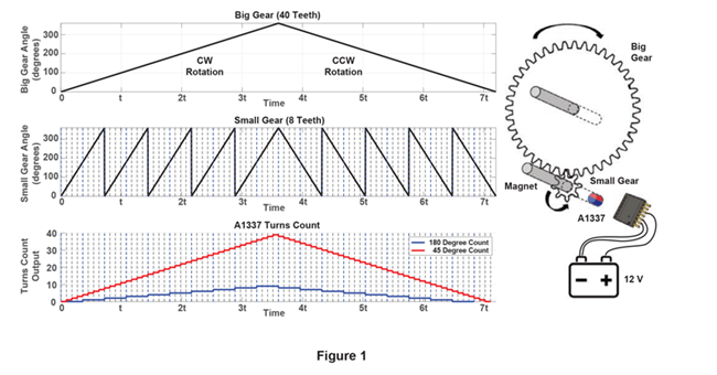
Often, these motor and seat-belt systems are geared down so that multiple angle sensor rotations need to be counted by the angle sensor IC. For this reason, the A1337 includes a circuit that counts the rotational turns of a magnet. When sensor ICs are connected to the car battery, they must also have low-power modes that enable efficient battery usage. Very often, a sensor IC must track the turns-count (TCs) of the magnet even when the vehicle is in the key-off state. The A1337 monitors and keeps track of TCs, even when set to Low Power Mode. This will ensure that the system can accurately and consistently track steering wheel position or seat-belt extension when using the A1337 in a key-on or key-off mode. Traditionally, this key-off requirement is achieved by a combination of relatively complex mechanical and electronic components. The A1337 can reduce system-level complexity and eliminate many system components by performing both the absolute angle measurement and the tracking of TCs, while maintaining low battery power consumption (85 μA) at vehicle key-off.
Overview of A1337
The A1337 is a 360° angle sensor IC that provides contactless high-resolution angular position information based on magnetic Circular Vertical Hall (CVH) technology. It has a system-on-chip (SoC) architecture that includes a CVH front-end, digital signal processing, and SPI, SENT, and PWM outputs. It also includes on-chip EEPROM technology for flexible end-of-line programming of calibration parameters. The A1337 is ideal for automotive applications requiring 0° to 360° angle measurements, such as electronic power steering (EPS), rotary shifters (PRNDLs), seat-belt tensioners, and throttle systems. The A1337 angle sensor device is designed to support a wide variety of applications and has multiple operating modes, organized by output format or by power consumption. By output format, the A1337 supports SPI, SENT, PWM, and Manchester interfaces. For each of these interfaces, the A1337 has the ability to report either the direct angle output (12-bit digital angle output reported over the selected output interface) or a Turns Count (TC) output, which is a quantized tracking count of the number of turns made by the magnetic target in either the clockwise or counter-clockwise direction. By power consumption, the A1337 features a Normal Power Mode, a Low Power Mode, and an ultra-low power Transport Mode.
Normal Power Mode
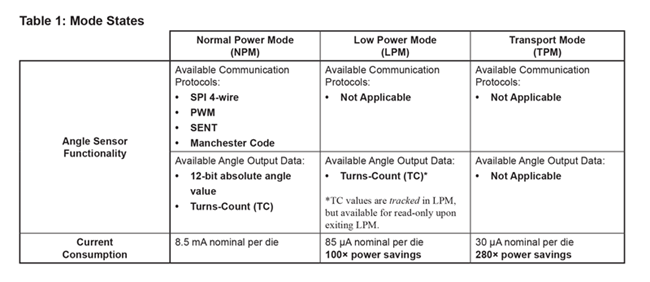
In Normal Power Mode, the IC draws maximum current (nominally 8.25 mA—see Normal Mode Supply Current specification in the A1337 datasheet for more details) to operate its full feature set, and updates the angle output register at the fastest rate as selected by RPM mode and AVG settings (see the A1337 programming
reference for more details).
Low Power Mode
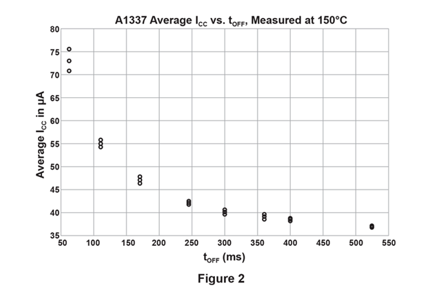
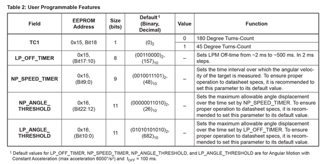
Low Power Mode is useful for battery-powered applications where the task of tracking the target’s rotation can be delineated into one of two mission modes. The first mission mode would be similar to an angle tracking mode, where the sensor tracks the output at full bandwidth and provides its measure of the angular output at full resolution. The second mission mode can be considered as a turns-tracking mode. In this mode, the sensor does not need to track the angle at full resolution—it is sufficient to track the Turns Count value of the target. The size of one turnscount unit can be preselected via EEPROM setting in the A1337 to be either 180 or 45 degrees. The A1337 tracks ±1280 turns in both directions. In Low Power Mode, the A1337 is mostly held in a lower quiescent current consumption state. The IC does not provide normal angle readings over the SPI, SENT, or PWM interfaces, but wakes up periodically to check for the occurrence of Turns Counts. The off-time of the Low Power Mode operation can be adjusted by the user based on the application, by programming on-chip EEPROM memory. Figure 2 shows Average ICC in μA versus the programmable off-time tOFF.
Transport Mode
Certain battery-powered applications require especially low power consumption from the IC during long-term storage and/or transportation (for example, when a new car is being transported from the assembly line to the dealer). To meet this need, the A1337 features an ultra-low power mode called Transport Mode. Transport Mode is used to put the A1337 into a deep-sleep state for ultra-low power consumption. When in this mode, the sensor IC does not track angle or turns counts. Typically, the IC consumes 30 μA of current per die when in Transport Mode.
WAKE Pin
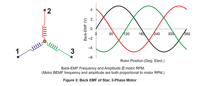
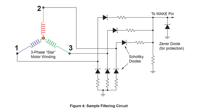
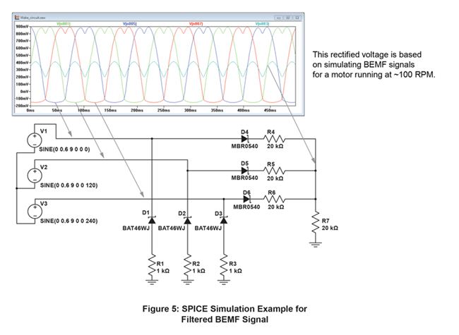
The A1337 also offers a WAKE input pin. This pin is intended to wake up the device from Low Power Mode, in special cases where the motor acceleration is too high, and the system cannot afford to wait for the entire Low Power Sleep time to expire, before the next periodic wakeup. When the voltage threshold on the WAKE pin exceeds VWAKE(HITH), the IC will wake up from Low Power Mode and begin to track Turns as it would in normal power mode. This pin is usually connected to a filtered version of the back-EMF voltage signal from the motor being used. This allows fast feedback from the motor to the Turns-Count circuit, in the case of high acceleration events. A symbolic waveform representation of the back EMF for a Star 3-phase motor, as well as a sample filtering circuit, are shown below.
Transitioning Between Modes
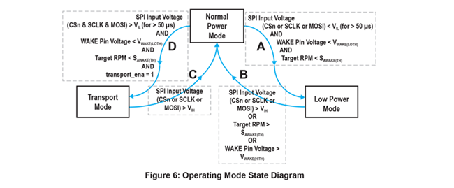
The A1337 is designed so that it can transition between Normal Power Mode (NPM), Low Power Mode (LPM), and Transport Mode (TPM) based on either a command from the system microcontroller, by magnetic target rotation, or by exceeding the WAKE pin threshold, VWAKE(HITH). This dual scheme ensures that valuable TC information is not lost due to the target rotating too quickly while the sensor is in Low Power Mode. To better understand this, consider a few scenarios based on
the state diagram shown in Figure 3, as well as the information shown in Table 1. Assume that the sensor is powered up and in NPM. It would therefore be able to provide all the functionality as described under NPM in Table 1. Now, if the controller decided that to save power it should enter LPM, then it would have to satisfy all the conditions outlined in branch A of Figure 3 in order to enter LPM. In other words, the A1337 SPI lines would have to be held low for >50 μs, the WAKE pin voltage
on the A1337 IC would have to be lower than the threshold VWAKE(LOTH), and the target RPM of the magnet would have tobe lower than an average speed SAWAKE(TH). If all these conditions were met, then the IC would transition into LPM. While in LPM, the IC would be able to support the TC tracking functionality
as described in Table 1. If the system now needed to wake up from LPM and re-enter NPM, it would need to then satisfy any one of the conditions outlined in branch B of Figure 3—in other words, initiating activity on SPI pins, or rotating the target faster than SAWAKE(TH), or applying a voltage higher than VWAKE(LOTH) on the WAKE pin. In a similar manner, the system can navigate between NPM, LPM, and TM, by meeting the appropriate conditions as specified by branches A, B, C or D of the state diagram.
User-Programmable Features for Low Power Mode and Turns Counting
Conclusion
