Improved Performance and Features of Allegro’s Next Generation, High Power Density CB Package Current Sensors
By Maxwell McNally
Allegro MicroSystems, LLC
Abstract
This application note will describe the use of the new high-current ACS772 Hall-effect current sensor integrated circuit (IC) from Allegro MicroSystems and will give an overview of its features and improvements from previous Allegro high-current sensors.
Introduction
The ACS772 is the newest in a long line of high-current measuring devices produced by Allegro MicroSystems. Housed in the Allegro proprietary CB package, the ACS772 offers ultrahigh power density, high inrush current capacity, and has factory-programmed options for sensing current in the range of 50 to 250 A. The CB package may be through-hole soldered directly onto the printed circuit board (PCB) which, along with the high isolation of the device, eliminates the need for expensive isolation techniques like optocouplers.
The ACS772 has an increased bandwidth of 200 kHz, some 80 kHz greater than that of its predecessor, the ACS770. Not only does the ACS772 respond faster to current transients, but it also has an increased accuracy and minimal drift over lifetime through proprietary compensation techniques. The identical pinout and operation of the device allow for dropin replacement of the ACS772 into ACS770 and ACS758 sockets.
CB Package and Isolation
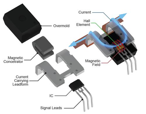
Internal to the CB package is a ferromagnetic concentrator that directs field from the current-carrying trace into the sensitive plane of the Hall element. Figure 1 indicates the different components that come together to form the CB package. Current travelling through the leadframe creates a magnetic field directed by the concentrator into the IC. The signal pins exit the overmolded package for connections to external circuitry.

Total Output Error and Lifetime Drift
Calibration within application, when possible, can be costly and limited to a customer’s end-of-line production system. To this end, Allegro has designed the ACS772 to have the lowest lifetime
drift of any CB current sensor to date. To account for the minimal lifetime drift of the ACS772, a new way of specifying total output error drift was devised. The ACS772 specifies a Total Output
Error Including Lifetime Drift, eliminating the need to add a drift value onto a nominal error specification.
The ACS772 has 0.9% less Total Output Error at room temperature and drifts over lifetime about 2% less than the ACS770. Table 1 below compares the ACS772’s total output error lifetime values to
those of the ACS770. It is important to note that the ACS770 is not specified in this way in the datasheet; a conversion has been made to the newer specification for easier comparison.
Table 1: Total Error Specifications for ACS770 and ACS772
| |
Total Output Error | Total Output Error Including Lifetime Drift |
|||||
| Temperature | DUT | Min. | Typ. | Max. | Min. | Typ. | Max. |
| 25°C to 150°C |
770 | –2.40% | ±1.5% | 2.40% | –4.30% | ±2.1% | 4.30% |
| 772 | –1.50% | ±0.9% | 1.50% | –2.10% | ±1.7% | 2.10% | |
| –40°C to 25°C |
770 | –3.50% | ±2% | 3.50% | –5.40% | ±2.6% | 5.40% |
| 772 | –3.50% | ±1.7% | 3.50% | –3.50% | ±2.6% | 3.50% | |
Temperature Ratings
Allegro current sensor ICs have a maximum junction temperature (TJ(MAX)) of 165°C and all ACS772 devices are tested at the ambient temperature (TA) of 150°C. Devices can operate safely at maximum ambient temperature so long as the maximum junction temperature specification is not violated. TA values are derated for devices in sustained high-current applications, as resistive heating is expected to push the internal temperature closer to the maximum junction temperature. These temperature codes, as explained in Table 2, appear in the part name directly after the
device number: ACS772LCB-050B-PFF-T.
Table 2: Allegro Temperature Codes
| CB Temperature Code |
Rated TA (°C) |
Current Sensing Range (A) |
Production Test Temperature (°C) |
| L | –40 to 150 | ±100 | 150 |
| K | –40 to 125 | ±150 | 150 |
| E | –40 to 85 | ±200 | 150 |
Supply Voltage Levels
The ACS772 is optimized at Allegro and programmed in production to operate at a supply voltage of 5 V. The ACS773 is optimized in the same way for 3.3 V supply rails. Reference the device datasheets located on the Allegro website for more information.
Having a device optimized for both 5 V and 3.3 V supplies allows the ACS772 and ACS773 family to replace any legacy device from Allegro, including the ACS758, ACS759, and ACS770.
Undervoltage Lockout
Undervoltage lockout (UVLO) prevents the ACS772 from operating outside of its optimized voltage range; it also gives diagnostic ability to the system about supply voltage drop. In order for the ACS772 and ACS770 to power-on correctly, the voltage must exceed a lockout threshold (VUVLOH) and stay above this level for a predetermined time (tUVLOD). If the device is not correctly powered, the output will remain at ground. Additionally, if the supply voltage drops below another threshold (VUVLOL) for long enough (tUVLOE), the output will pull to ground and the part must be repowered. An output voltage of 0 V is outside of the expected range of the device and may indicate the sensor is operating outside of the supply voltage specification. This is implemented on the 5 V device (the ACS772).
The 3.3 V ACS773 has a power-on reset (POR) instead. This acts largely in the same manner, except that there is no timer when dropping below a low threshold. The device shuts off immediately and goes into a high impedance state.
Ratiometry
The ratiometric output of the ACS772/3 scales in accordance with changes in supply voltage. Applications with an ADC referenced to the same supply voltage as the current sensor IC have reduced measurement error due to changes in VCC. The entire highcurrent portfolio of the ACS758, ACS770, and ACS772 have ratiometric outputs that provide this improved performance.
Bandwidth and Response Time
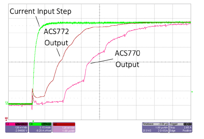
The ACS772/3 have an increased bandwidth of 200 kHz compared to the 120 kHz bandwidth of its predecessors. This allows the device to respond faster to current transients, which is highlighted in Figure 2, while the exact values of response time parameters are compared in Table 3.

Table 3: Response Time Comparison
| Specification | Rise Time (μs) | Propagation Delay (μs) |
Response Time (μs) |
| ACS772 | 2.4 | 1.2 | 2.5 |
| ACS770 | 4.1 | 2.4 | 4.6 |
| ACS758 | 3.0 | 1.0 | 4.0 |
Noise Performance
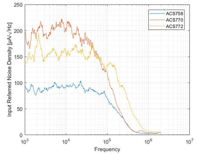
It could be expected that higher bandwidth entails higher noise, but the ACS772 not only has an increased bandwidth but maintains similar noise performance to the ACS770. Table 4 below compares typical noise values and calculates both 200 kHz and 120 kHz filtered operation of the ACS772.
Table 4: Noise Comparison
| Part Number | Noise Density (μA / √Hz) |
Bandwidth (kHz) |
RMS Noise (mARMS) |
| ACS772 | 160 | 200 | 90 |
| 120 [1] | 70 | ||
| ACS770 | 190 | 120 | 83 |
| ACS758 | 90 | 120 | 37 |
[1] Filtered to compare with lower bandwidth ACS770 and ACS758 devices.
The noise of each device is best shown in Figure 3, where the noise densities are compared. Each of these devices were rated for 150 A with an identical gain of 13.33 mV/A.

Conclusion
Allegro next-generation ACS772 and ACS773 devices in the CB package offer faster response time and improved accuracy over a wide operating temperature range for their entire lifetime. These sensors are ideal for applications that require these nextgeneration improvements, and are offered with a variety of current ranges and supply voltages to meet any application need. Identical package and operation allow the ACS772 and ACS773 to be a drop-in replacements to the Allegro ACS758, ACS759, and ACS770 devices.
